The limiting shear stress for the bolts is , and a factor of safety of is required. The allowable shear stress is therefore:
The cross-sectional area of a diameter bolt is . When used in a double shear connection, two cross-sectional surfaces of the bolt are subjected to shear stress. The allowable bolt shear force (denoted ) is therefore:
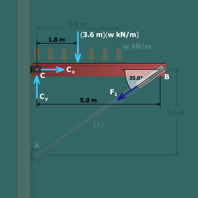
The shear force acting on bolts and is equal to the axial force in member . As shown previously, the force in member can be expressed in terms of as: