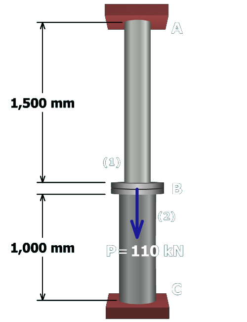
The figure shows a vertical rod A B labeled 1 attached to a vertical post B C labeled 2 by a flange at B. The length of member 1 is 1500 millimeters and the length of member 2 is 1000 millimeters. The load at B is P which equals 110 kilo newtons directed vertically downwards. The rod is attached to a rigid support at A and the post is attached to a rigid support at C.

A steel rod (1) is attached to a steel post (2) at flange B. A downward load of 110 kN is applied to flange B. Both rod (1) and post (2) are attached to rigid supports at A and C, respectively.

Rod (1) has a cross-sectional area of 800 mm2 and an elastic modulus of 200 GPa. Post (2) has a cross-sectional area of 1,600 mm2 and an elastic modulus of 200 GPa.

• Compute the normal stress in rod (1) and post (2).

• Compute the deflection of flange B.