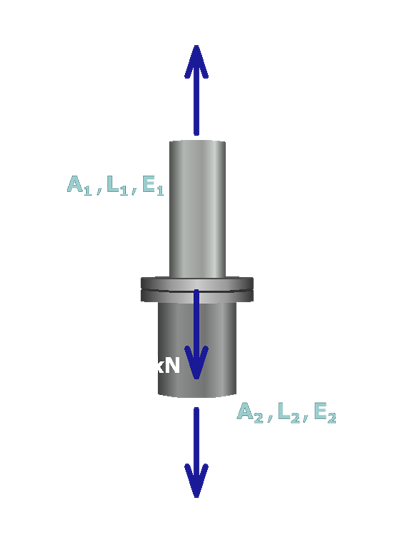
Two equations have been derived for this structure. An equilibrium equation
and a compatibility equation
These two equations can be solved simultaneously to determine the internal forces in members and .

Two equations have been derived for this structure. An equilibrium equation
and a compatibility equation
These two equations can be solved simultaneously to determine the internal forces in members and .