Home
Chapter 5: Axial Deformation
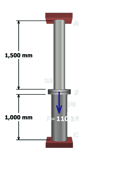
M5.5: Rod and Post in Series
Free-Body Diagram at Flange B
State the Problem
Table of Contents
Free-Body Diagram at Flange B
Equilibrium Equation
Geometry of Deformations Equation
Force-Deformation for Members (1) and (2)
Compatibility Equation
Two Equations in Terms of F
1
and F
2
Solve for F
1
and F
2
Calculate F
1
and F
2
Calculate Normal Stresses
Solve for Deflection at B
Finished
Try One
scene
3
of
14
To solve this problem, first consider equilibrium. Draw a free-body diagram around flange
B
.