Home
Chapter 5: Axial Deformation
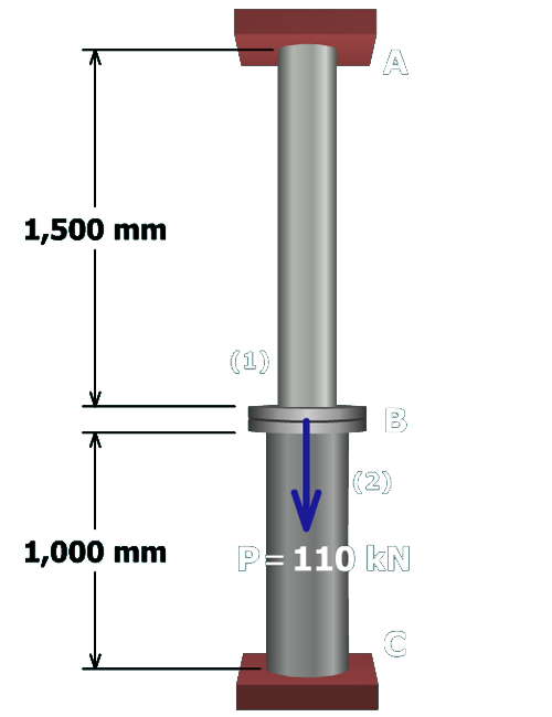
M5.5: Rod and Post in Series
Finished
State the Problem
Table of Contents
Free-Body Diagram at Flange B
Equilibrium Equation
Geometry of Deformations Equation
Force-Deformation for Members (1) and (2)
Compatibility Equation
Two Equations in Terms of F
1
and F
2
Solve for F
1
and F
2
Calculate F
1
and F
2
Calculate Normal Stresses
Solve for Deflection at B
Finished
Try One
scene
13
of
14
F
1
=
27
.
5
kN
(
T
)
σ
1
=
34
.
4
MPa
(
T
)
Flange
B
deflects
0
.
258
mm
(downward)
F
2
=
82
.
5
kN
(
C
)
σ
2
=
51
.
6
MPa
(
C
)
Finished