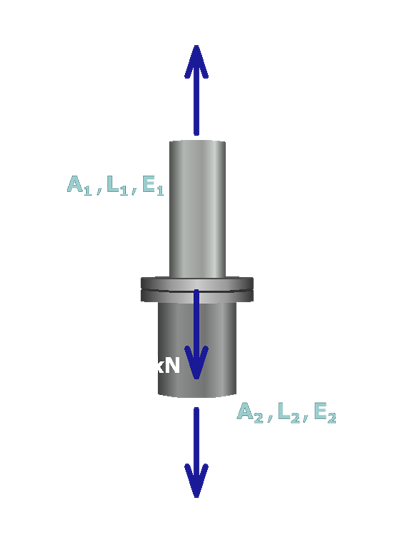
The figure shows the free body diagram around flange B. The free body diagram cuts through members 1 and 2. The load on the flange is P which equals 110 kilo newtons directed vertically downwards. The reaction force on member 1 is F subscript 1 directed vertically upwards. The reaction force on member 2 is F subscript 2 directed vertically downwards. The parameters corresponding to member 1 are A subscript 1, L subscript 1 and E subscript 1 and the parameters for member 2 are A subscript 2, L subscript 2 and E subscript 2.

Substitute

δ1=F1L1A1E1

and

δ2=F2L2A2E2

into the geometry of deformations equation

δ1+δ2=0

to obtain the following equation:

F1L1A1E1+F2L2A2E2=0

This equation relating F1 and F2 is called the compatibility equation.