The figure shows the free body diagram around flange B. The free body diagram cuts through members 1 and 2. The load on the flange is P which equals 110 kilo newtons directed vertically downwards. The reaction force on member 1 is F subscript 1 directed vertically upwards. The reaction force on member 2 is F subscript 2 directed vertically downwards. The parameters corresponding to member 1 are A subscript 1, L subscript 1 and E subscript 1 and the parameters for member 2 are A subscript 2, L subscript 2 and E subscript 2.

Write force-deformation relationships for each of the axial members. For consistency, we will always assume that the internal force in an axial member is tension. Thus, a positive deformation corresponds to elongation in the axial member.
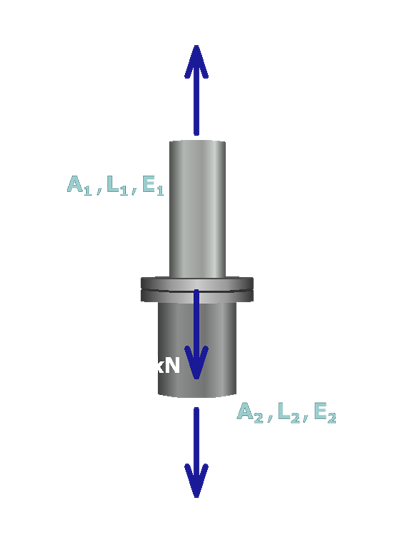
For member (1), the force-deformation relationship can be written as:

δ1=F1L1A1E1

and for member (2):

δ2=F2L2A2E2