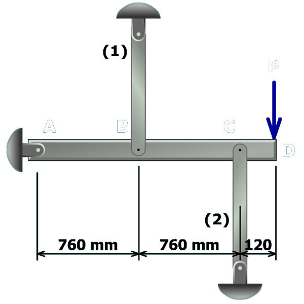
 To solve this problem, a five-step procedure will be used.
Step 2 – Geometry of deformation equation
(a) Draw the rotated position of the rigid bar and determine the relationship of the rigid bar deflections at and from similar triangles.
(b) Sketch the axial members after the rigid bar has rotated about . Determine the final length of each bar in terms of its initial length and the appropriate rigid bar deflection.
(c) Relate the member elongations to the rigid bar deflections.