 To solve this problem, a five-step procedure will be used.
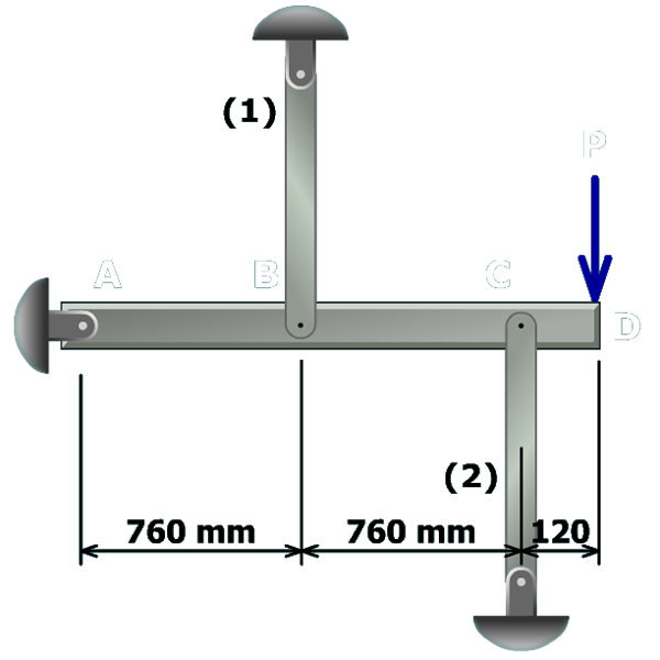
Step 3 – Force-deformation relationships
Write the general force-deformation relationship for each axial member.
To solve this problem, a five-step procedure will be used.
Step 3 – Force-deformation relationships
Write the general force-deformation relationship for each axial member.