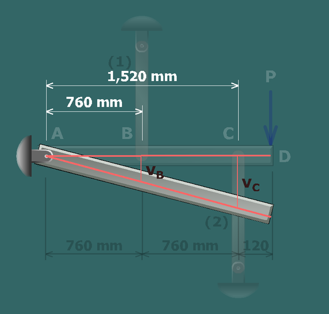
To determine the geometry of deformation relationship, first sketch the rotated position of rigid bar after load has been applied.
Since member is connected to the rigid bar at and member is connected to the rigid bar at , the relationship between the rigid bar deflections will be determined at those joints.
Using the principle of similar triangles, the rigid bar deflections are related as: