Diagram shows an aluminum shaft A B marked 1 and a brass shaft B C marked 2 with a flange in between at B. Both the shafts are centered on the central axis x. The shaft is supported at A and C. A torque T is applied at B. The radial and longitudinal lines are shown on the shaft. The deformation of the shaft is shown with a clockwise segment at C of angle phi subscript 2, angle of twist. A caption to the bottom left of the shaft 1 reads: phi subscript 1 = phi subscript B. A caption to the bottom left of the shaft 2 reads: phi subscript 2 = negative phi subscript B.

The angles of twist in shafts (1) and (2) expressed in terms of rotation angles are therefore:

ϕ1=ϕBϕ2=-ϕB

Add these two equations to obtain the geometry of deformation equation:

ϕ1+ϕ2=0

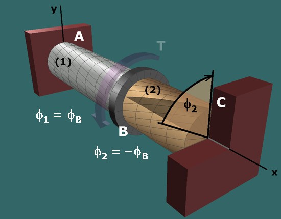
This equation expresses the relationship between the angles of twist in the two shafts for the given support conditions.