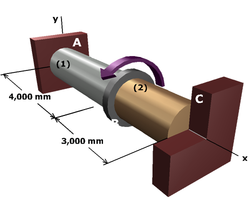
Diagram shows an aluminum shaft A B with a support at A, marked 1 of length 4,000 millimeters and a brass shaft B C with a support at C, marked 2 of length 3,000 millimeters with a flange in between at B. The shafts are centered on the x axis. A torque T is applied at B.

Substitute the torque-twist relationships...

ϕ1=T1L1J1G1     and    ϕ2=T2L2J2G2

...into the geometry of deformation relationship...

ϕ1+ϕ2=0     

...to obtain the compatibility equation:

T1L1 J1G1+T2L2 J2G2=0

This equation is based upon the deformations that will occur in the composite shaft, expressed in terms of the unknown internal torques T1 and T2.