Diagram shows an aluminum shaft A B marked 1 and a brass shaft B C marked 2 with a flange in between at B. Both the shafts are centered on the central axis x. The shaft is supported at A and C. A torque T is applied at B. The radial and longitudinal lines are shown on the shaft. The deformation of the shaft is shown with a clockwise segment at C of angle phi subscript 2, angle of twist. A caption at the bottom left reads: phi subscript 2 = phi subscript C minus phi subscript B.

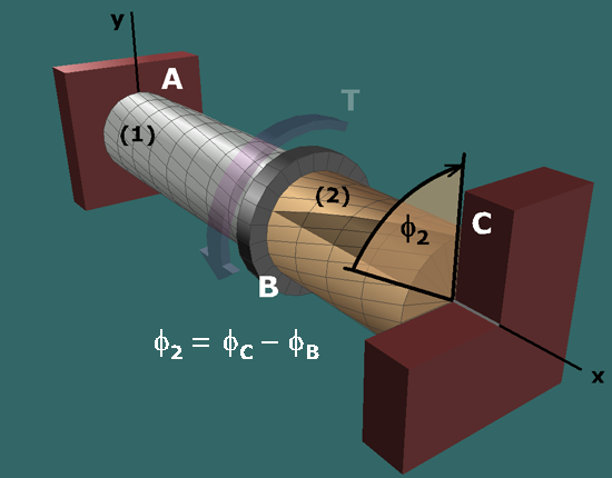
The angle of twist in shaft (2) can be expressed as:

The angle of twist in a shaft can be determined by considering the angles of rotation at its two ends.

Moving in the +x axis direction from A to B, the angle of twist is simply the rotation angle at the forward end B minus the rotation angle at the aft end A:

ϕ1=ϕB-ϕA

Since A is a fixed support, the rotation angle at A is φA = 0. Therefore:

ϕ1=ϕB