Home
Chapter 6: Torsion
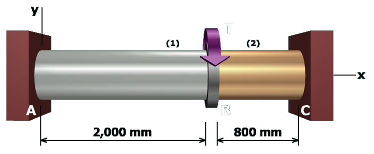
M6.23: Shafts With Specified Rotation Angle
Equilibrium
State the Problem
Plan the Solution
Table of Contents
Review Sign Conventions
Equilibrium
Geometry of Deformation
Torque-Twist Relationships
Section Properties
Solve for T
1
and T
2
Compute Shear Stresses
Finished
scene
5
of
11
Draw a
FBD
around flange
B
.