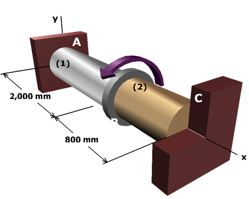
In summary, the internal torques in shafts (1) and (2) are:
The maximum torque T that can be applied to flange B without exceeding a rotation angle of 3° is:
Shear stress magnitudes are:
Finished

In summary, the internal torques in shafts (1) and (2) are:
The maximum torque T that can be applied to flange B without exceeding a rotation angle of 3° is:
Shear stress magnitudes are:
Finished