The shear stress in a shaft is given by the elastic torsion formula:
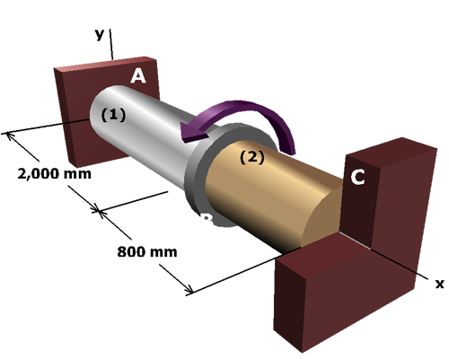
Using the values computed for T1 and T2, calculate the shear stresses in each shaft:

The shear stress in a shaft is given by the elastic torsion formula:
Using the values computed for T1 and T2, calculate the shear stresses in each shaft: