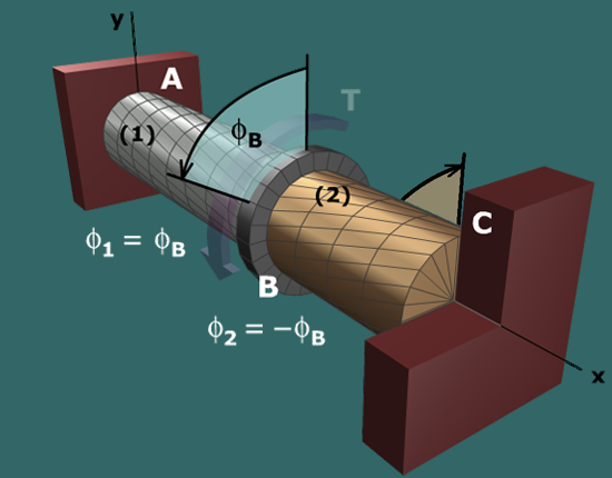
Diagram shows an aluminum shaft A B marked 1 and a brass shaft B C marked 2 with a flange in between at B. Both the shafts are centered on the central axis x. The shaft is supported at A and C. A torque T is applied at B. The radial and longitudinal lines are shown on the shaft. The deformation of the shaft is shown with a counterclockwise segment at B of angle phi subscript B, angle of twist. A caption to the bottom left of the shaft 1 reads: phi subscript 1 = phi subscript B. A caption to the bottom left of the shaft 2 reads: phi subscript 2 = negative phi subscript B.

The angle of twist in shaft (1) and (2) expressed in terms of rotation angles are therefore:

ϕ1=ϕBϕ2=-ϕB

Since the rotation angle at B is known (i.e., ϕB=3), the above relations can be combined with the torque-twist relationships...

ϕ1=T1L1J1G1   and   ϕ2=T2L2J2G2

...to compute the internal torques T1 and T2 in the stainless steel and bronze shafts. Once these internal torques are known, the torque T can be computed from equilibrium and the shear stress in each shaft can be calculated with the torsion formula.