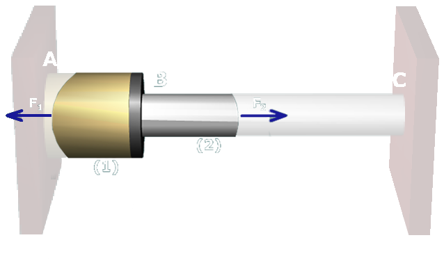
Step 1. Equilibrium equation
Drag the proper equilibrium equation here!!!

Drag the proper equilibrium equation here!!!
While this equilibrium equation could be used, in our method we always assume tension forces in the axial members.
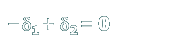
Correct. This equilibrium equation is based on the assumption that tension forces act in both axial members.
This equilibrium equation includes an external force P. Once the flange is bolted to the brass post, there is no external force.
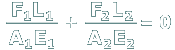
While this equation includes the internal forces in members 1 and 2, it is actually a compatibility equation. Notice that the two terms are expressions of the deformation in each axial member.
This equation expresses a relationship between the deformations in members 1 and 2. It is an example of a geometry of deformation equation.