Step 4. Compatibility equation
Drag the proper compatibility equation here.


Drag the proper compatibility equation here.
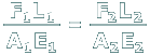
This is a geometry of deformation equation. The compatibility equation is derived by substituting the force-deformation relationships into the geometry of deformation equation.
This is a compatibility equation, but it does not correspond with the geometry of deformation equation that was found in the previous scene.
This equation makes no sense. The terms on the left are forces while the term on the right is a length unit.
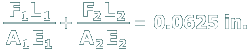
Correct. The force-deformation equations are substituted into the geometry of deformation equation. The result is an equation based on the deformations that will occur for this configuration, but it is expressed in terms of the unknown forces F1 and F2.
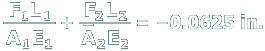
The left-hand side of this equation is correct but the gap distance appearing on the right-hand side should be a positive quantity.