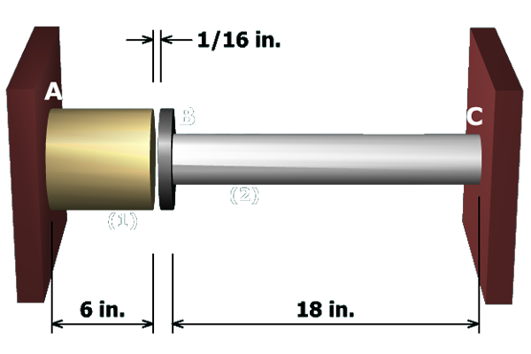
The internal force in each of the axial members has been determined:
The normal stress in each axial member can now be computed.
and
Finished
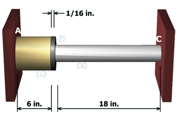
The internal force in each of the axial members has been determined:
The normal stress in each axial member can now be computed.
and
Finished