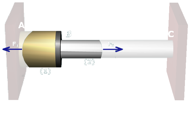
Step 3. Force-deformation relationships
Drag the proper force-deformation equation here.
Drag another proper force-deformation equation here.


Drag the proper force-deformation equation here.
Drag another proper force-deformation equation here.
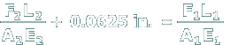
This is a compatibility equation, which is expressed in terms of the unknown internal member forces.
This geometry of deformation equation expresses a relationship between the deformations in members (1) and (2).
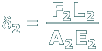
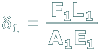
Correct. This equation states the relationship between the internal force in an axial member and its deformation.
This geometry of deformation equation expresses a relationship between the deformations in members (1) and (2).
Correct. This equation states the relationship between the internal force in an axial member and its deformation.