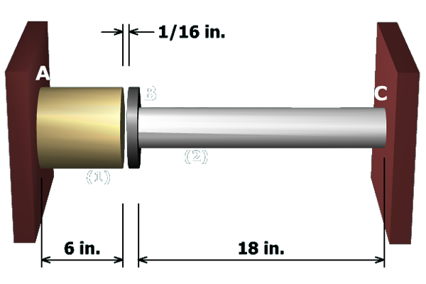
Compute the stresses induced in the aluminum rod and the brass post when the gap between flange and the brass post is closed by bolts.
Compute the stresses induced in the aluminum rod and the brass post when the gap between flange and the brass post is closed by bolts.