Step 2. Geometry of deformation equation
Drag the proper geometry of deformation equation here.


Drag the proper geometry of deformation equation here.
This equation does not correctly relate the deformation that occurs in members (1) and (2). Hint: The 0.0625-in. gap appears in the correct geometry of deformation equation.
This equation states that the deformation in member (2) plus an additional 0.0625 in. equals the deformation in member (1). This is clearly too much deformation.
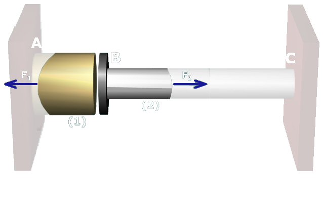
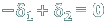
Correct. The deformations that occur in members (1) and (2) add up to a total of 0.0625 in.
This equation states that the deformation in member (2) plus an additional 0.0625 in. equals the deformation in member (1). This is clearly too much deformation.
This equation does not correctly relate the deformation that occurs in members (1) and (2). Hint: The 0.0625-in. gap appears in the correct geometry of deformation equation.