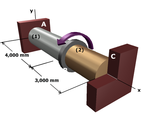
We will pick one of the shafts and assume that its shear stress is equal to its allowable stress. Using the relationship above, we will compute the corresponding shear stress in the other shaft.
If its shear stress is less than its allowable shear stress, we have guessed correctly and we can proceed to solve the problem.
If its shear stress is greater than its allowable shear stress, we have guessed incorrectly and we must revise our stress calculations before we proceed.
Note: With allowable stresses, it is customary to consider only the stress magnitude, not the sign. In comparing shear stresses with allowable stresses, therefore, we consider absolute values of and .