The stress in shaft controls the capacity of the composite shaft. Accordingly, set .
Note: The negative value is used here to be consistent with the direction of the external torque applied to flange as shown in the sketch.
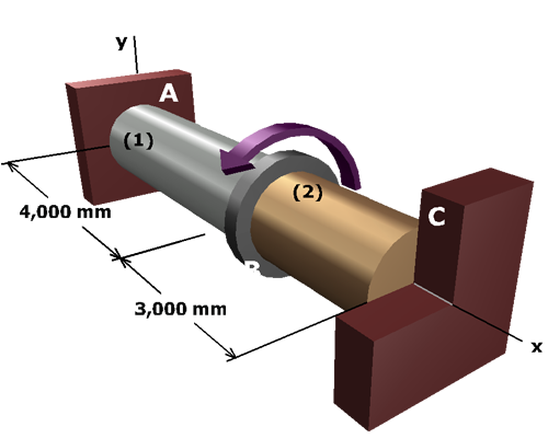
Compute the shear stress in shaft :