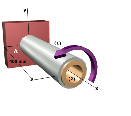
The procedure to solve this problem can be outlined as:
• Compatibility equation
The torque-twist relationships will be substituted into the geometry of deformation relationship to derive a compatibility equation expressed in
terms of the internal torques and .
• Stress relationship
Expressions for shaft torques can be obtained from the elastic torsion formula. Substituting these expressions into the compatibility equation gives a relationship between the shear stresses in the shafts.
• Controlling shear stress
Using the relationship between shear stresses in the two shafts and the allowable stresses, the shaft that controls the design can be determined.