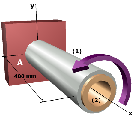
Let's assume that shaft controls. We will assume that the shear stress in shaft is equal to its allowable stress.
Based on this assumption, the shear stress in shaft must be:
Since the shear stress is greater than the allowable shear stress for shaft , our initial assumption is incorrect. Shaft will actually control the capacity of the composite shaft. The shear stress magnitude in shaft will equal its allowable stress.